WS2 FLASH CODES
What are flash codes?
Flash codes is the name given to fault codes or trouble codes that are read by counting flashes of the check engine light or ABS warning light. Flash codes provide diagnostic information for troubleshooting problems. Only vehicles with an on board computer may detect flash codes.
How to extract codes?
To extract the codes, the first step to do is obtain the work shop manual to that particular vehicle you would be extracting the codes from. In this case the vehicle I worked on is a, Toyota Corolla 4 A-FE.
The procedure to extract the codes is as follows:

When you turn the ignition key to ON position but with the engine not running the check engine light will light up on the dashboard. Then when you start the engine the check light should go off. If the check engine light remains on, then the diagnosis system has detected a fault in the system.

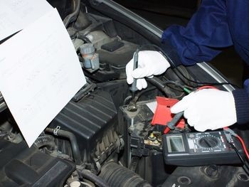
To find what fault the system holds you would have to turn the ignition key on, engine off, and find the diagnostic plug to connect two terminals using a jumper wire. On the engine I worked on terminals TE1 and E1 had to be connected. This puts the computer into diagnostic mode. The check engine light would then flash. By carefully counting the flashes and pauses a numeric code represents what diagnostic chart to refer to in the work shop manual. For example four flashes pause then one flash equals “41”. Two flashes pause then one flash equals “21”. Now referring to the chart in the manual, fault code “41” relates to throttle position sensor circuit and fault code “21” relates to the oxygen sensor circuit.

Once you know what code the system holds you can begin locating the fault step by step and find out what caused it.
There are several factors that can cause DTCs for a oxygen sensor. A contaminated o2 sensor will not produce the proper voltages and will not switch properly. The sensor can be contaminated from engine coolant, excessive oil consumption, additives used in sealants, and the wrong additives in gasoline. The sensor becomes lazy then takes a longer time to switch. This will affect emissions and can produce driveability problems.
Things like vacuum leaks, EGR leak, excessive fuel pressure, can affect the operation of the oxygen sensor.
Ws7 exhaust analysis
Ws7 exhaust gas analysis (petrol only)


What are emissions?
When fuel is consumed it emits substances in to the air. These fuel emissions can be very harmful to the environment and to the lives of humans, plants and animals. When fuel in a petrol engine is burned it releases harmful substances such as hydrocarbons HC, carbon monoxide CO and NOX nitrous oxide.
In addition to these harmful emissions carbon dioxide CO2 and oxygen O2 are also produced and when testing a vehicles emissions, can provide information on what’s going on inside the combustion chamber.
First task to do was to sense normal air using the analyzer probe and record the four gas readings and what they mean.
CO: 0.001% means: carbon monoxide is measured in percent or parts per hundred. CO is a by-product of combustion, therefore if combustion does not take place CO will not be created. Based on this, when a misfire occurs, the co that would have normally been produced during the production process is not produced. So basically on fuel-injected vehicles, high co means too much fuel is being delivered to the engine for the amount of air entering the intake manifold.
HC: 12ppm means: hydrocarbons, which are measured in parts per million (ppm). HC is unburned fuel that remains as a result of a misfire. When combustion doesn’t take place or when only part of the air/fuel charge burns, hydrocarbon levels goes up.
Co2: 0.00% means: carbon dioxide measured in percent or parts per hundred. Co2 is a by-product of efficient and complete combustion. Near perfect combustion will result in co2 levels, which approach the theoretical maximum of 15.5%.
02: 20.9% means: oxygen, which is measured in percent or parts per hundred. The amount of oxygen produced by an engine is affected by how close the air/fuel ratio is to stoichiometry. As the mixture goes lean of stoichiometry, o2 increases. As mixture goes rich, o2 falls close to zero. Because o2 is used up during combustion, o2 levels at the tail pipe will be low. If misfire occurs, however, oxygen will increase dramatically as it passes unused through the combustion chamber.
The next task was to measure the four gas readings on a cold engine while idling.
CO: 2.8% HC: 778ppm CO2: 12.6% O2: 5.15%
the readings above show CO reading of 2.8% that means there is a high amount of fuel being delivered to the engine for the amount of air entering the intake manifold. This is because the engine is cold. There is high amount of HC which means not all the fuel is being burnt inside the engine or because the catalytic converter has not reached operating temperature. The CO2 shows that there is a low amount of misfires and that the engine is running efficient. The 02 readings show that there is a lean air/fuel mixture.
Now with the engine warmed up idling.
CO: 0.50% HC: 295ppm CO2: 14.5% O2: 1.10%
CO indicates combustion is taking place, HC shows that most of the fuel is being burnt. CO2 shows that the carbon from the fuel is fully oxidized during combustion therefore misfires are low and the engine is running efficient. There is a low amount of O2 produced from the engine, which shows that the air/fuel ratio is gone rich of stoichiometry.
Now running the engine at 2600 RPM
CO: 0.234% HC: 121ppm CO2: 15.10% O2: 0.32%
HC shows most of the fuel is being burnt. High co2 of 15.10% means the fuel is fully oxidized during combustion. These values show complete combustion. Near perfect combustion will result in co2 levels which approach the maximum of 15.5%. co levels show that good combustion is taking place because if combustion does not take place co will not be created.
Now while idling we sprayed propane into the fuel filler to make the mixture rich.
co: 1.859% HC: 197ppm CO2: 14.07% O2: 0.79%
the readings show high levels of carbon monoxide CO which is caused by anything that can make the air/fuel mixture richer than ideal. An increase in co doesn’t mean there will be an increase in HC. HC will only be created at the point where rich misfire begins (3% to 4% CO). co2 level shows good combustion is taking place. O2 level shows the oxygen is being burnt.
The rest of my BLOG I have copied the questions from my practical work book so it would be more understandable.
Disconnect one spark plug wire, ground it with a jumper wire, and then record the Four Gas readings as the engine idles:
Explain what is happening within the engine referring to the four gases:
CO: 0.01 HC: 1033ppm CO2: 13.6% O2: 4.53%
the cylinder that the spark plug wire got grounded to could not ignite the fuel in the combustion chamber because it was grounded to the cylinder head. This caused that cylinder to misfire and not burn the fuel that was injected and the air that entered the combustion chamber. As a result the HC ppm levels were as high as 1033ppm which is because there was 1 cylinder miss firing every four strokes and so waste allot of gas and oxygen.
the cylinder that the spark plug wire got grounded to could not ignite the fuel in the combustion chamber because it was grounded to the cylinder head. This caused that cylinder to misfire and not burn the fuel that was injected and the air that entered the combustion chamber. As a result the HC ppm levels were as high as 1033ppm which is because there was 1 cylinder miss firing every four strokes and so waste allot of gas and oxygen.
If you can get to it, disconnect the injector harness connector from one injector on an engine that has one injector for every cylinder: Record the Four Gas readings as the engine idles:
Explain what is happening within the engine referring to the four gases:
CO: 0.009% HC: 53ppm CO2: 11.61% O2: 5.45%
the engine is running lean. One injector is disconnected and so in that cylinder on the intake stroke only air is entering the combustion chamber. O2 levels are high because it is not being mixed with fuel and burnt in the cylinder with the missing injector.
the engine is running lean. One injector is disconnected and so in that cylinder on the intake stroke only air is entering the combustion chamber. O2 levels are high because it is not being mixed with fuel and burnt in the cylinder with the missing injector.
Explain the different readings you would get from a vehicle with a catalytic converter and a vehicle without one and why?
A vehicle with a catalytic converter converts harmful HC + CO + NOx into harmless compounds such as H2o, CO2 and N2. A vehicle without one may only reduce some compounds like NOX levels using an EGR valve. But a vehicle without a catalytic converter does not reduce as much emissions as a vehicle with one does.
A vehicle with a catalytic converter converts harmful HC + CO + NOx into harmless compounds such as H2o, CO2 and N2. A vehicle without one may only reduce some compounds like NOX levels using an EGR valve. But a vehicle without a catalytic converter does not reduce as much emissions as a vehicle with one does.
Explain what light off point means and what happens?
Light off point is when the catalytic converter has reached its operating temperature and starts to reduce emissions.
Light off point is when the catalytic converter has reached its operating temperature and starts to reduce emissions.
On lambda, 02 sensors why do they have 1,2,3,4 or 5 wires and what do these extra wires do?
They have 2 white wires which are heater + and heater - which heat the sensor to get it up to operating temperature so it responds quicker. The 3rd wire is black wire which is a signal wire to the ECU which tells it how much free o2 there is in the exhaust gases. The 4th wire is grey which is the signal earth wire
They have 2 white wires which are heater + and heater - which heat the sensor to get it up to operating temperature so it responds quicker. The 3rd wire is black wire which is a signal wire to the ECU which tells it how much free o2 there is in the exhaust gases. The 4th wire is grey which is the signal earth wire