ABS is fitted to vehicles to prevent the wheels from locking during heavy braking conditions. This will generally reduce the stopping distance and provide safer driving.
Overview of ABS
ABS controls the hydraulic pressure of all 4 wheels during sudden braking and when braking on slippery or uneven road surfaces.
Without ABS, when the brakes are suddenly applied, the wheels can lock and the tyre will skid. This causes the vehicle to veer to the side where the tyre has the greatest friction with the road surface.
With ABS working, the wheels are prevented from locking during braking. The vehicle stays straight, and the stopping distance is reduced. It prevents the brakes from locking and the wheels from skidding by modulating the hydraulic pressure in the brake system. It can hold the brake pressure, decrease the brake pressure or restore it to provide the most effective braking for the road conditions.
http://www.youtube.com/watch?v=ngKSirE7zJA
http://www.youtube.com/watch?v=ngKSirE7zJA

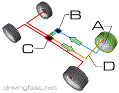
The location of the main parts of an anti lock braking system are shown in the picture above. The master cylinder assembly and the disc brake assemblies at the wheels are normal brake-system components. The ABS parts of the system are the:
1. Hydraulic control unit
2. Electronic control unit (ABS computer)
3. Speed sensors at the wheels
4. Electrical circuit
Operation
When the brakes are applied the sensors supply wheel speed information to the ABS computer, the computer then operates the hydraulic unit and the hydraulic unit adjusts the pressure at the brakes to prevent the wheels from skidding.
Hydraulic control unit:
The hydraulic unit is used to control brake pressure. It has eight solenoid valves – two for each hydraulic circuit of 4-channel system.
For all normal braking, when the ABS is not operating, pressure from the master cylinder reaches the hydraulic control unit and passes on through the brake lines to the wheels cylinders.
When the ABS comes into operation, fluid pressure from the master cylinder is controlled by closing and opening the solenoid valves at the appropriate times, so that it provides maximum braking, but at the same time prevents skidding.
ABS Channels
Channels refer to the lines, or circuits, to the wheels.
Three-channels:
Vehicles with a rigid rear axle have a three-channel system while those with independent rear suspension have a four-channel system.
A three-channel system has a hydraulic line and a sensor at each wheel. The hydraulic control unit has a pair of solenoid valves for each front wheel, but only one pair of solenoid valves for both rear wheels.
With a rigid rear axle-axle, each rear wheel has its own sensor, but there is only one channel to serve both wheels. So, if the pressure at one wheel has to be altered, the pressure at both wheels will be altered.
Four-channel:
With independent suspension at both the front and the rear of the vehicle, a four-channel system can be used. Each wheel has its own sensor and its hydraulic line. The hydraulic control unit has separate solenoids and valves for each channel; therefore each wheel can be controlled independently. There are two solenoid-operated valves for each channel.
Where a vehicle has independent suspension at both front and rear, the pressure at each of the wheels is adjusted separately.
The above picture shows a four-channel system.
Speed sensors at the wheels
There are three main types of wheels sensors on modern vehicles. One sends an analogue signal using an inductive pick up; the others send a digital signal using either Hall Effect or magneto resistance encoder.

The picture above shows a magnetic pick up sensor and tooth rings that are used with an independent rear suspension. The pulse rings are mounted to the differential housing and the pulse rings are fitted to the drive shafts. Independent rear suspension enables a four-channel system to be used.
The wheel hub or drive shaft has a pulse ring (toothed rotor) that rotates with the wheel and a sensor that is mounted close to it. As each tooth of the pulse ring passes under the sensor, a small voltage pulse is induced in the sensor. The pulses are sent as input signals to the electronic control unit.
The frequency of the pulses is related to road speed, and the control unit uses these signals to determine the rate of deceleration which could produce skidding. If the brake is about to lock, the pressure is relieved for a moment and skidding is prevented.
Electronic system
The electronic control system has sensors at the wheels and an Electronic control unit in the engine compartment. The wheel sensors send speed signals to the control unit, which monitors them and decides when wheel lock is about to occur.
Before the wheel locks the electronic control unit operates a solenoid in the hydraulic control unit. The solenoid valve reduces the hydraulic pressure to the brake of that particular wheel and so prevents the brake from locking and the wheel from skidding. When the possibility of skidding has been overcome, the solenoid is again operated to restore normal brake pressure at the wheel.
Operating modes
The hydraulic system has three operating modes. In operation the, the pressure is quickly changed from one mode to the other, as required, to obtain the maximum braking effect without locking the wheels, the fluid pressure modes are:
1. non- ABS braking pressure
2. holding pressure
3. reducing pressure
4. Increasing (restoring) pressure.
The inlet and outlet valves control the fluid in the hydraulic control unit. They are solenoid valves that can be opened or closed by energizing their solenoids. This is done by an electric signal from the electronic control unit. The inlet valves are normally opened, but are closed when their solenoids are energized. The outlet valves are normally closed, but are open when their solenoids are energized. Each valve can be operated independently
By signals from the electronic control unit
The inlet valves control pressure fluid to the brakes, and the outlet valves control pressure fluid from the brakes.
Non – ABS braking pressure
During normal braking the solenoids are not energized so the pressure holding valve remains open and the pressure reduction valve remains closed.

When the brakes are being used normally and there is no ABS action required, the system acts as follows:
1. The inlet valves are held open and the outlet valves are held closed.
2. When the brakes are pressed, fluid flows through the open inlet valve to the wheel cylinders to apply the brakes in the normal way.
3. When the brake pedal is released, fluid flows back through the inlet valve to release the brakes.
4. Braking occurs in the usual way, with pressure in the system dependent on the force applied to brake pedal by driver.
Holding pressure
The pressure reduction valve closes, preventing hydraulic fluid from going to the reservoir
 http://www.autoshop101.com/forms/brake09.pdf
The pressure reduction valve closes, preventing hydraulic fluid from going to the reservoir

When the electronic control unit detects the sudden deceleration of a wheel, indicating that the wheel is about to skid, it signals the hydraulic control unit to hold the pressure at the brake.
1. The outlet valve is already closed and the signal from the electronic unit closes the inlet valve.
2. Fluid under pressure is then held in the part of the circuit between the inlet valve, the wheel cylinder and the outlet valve.
3. This pressure will remain constant regardless of any change in pressure at the master cylinder as long as the outlet valve remains closed.
Reducing pressure
 http://www.autoshop101.com/forms/brake09.pdf

When the slip ratio of any wheel exceeds 30%, the ABS ECU energizes both the holding valve and the reduction valve.
If the electronic control unit detects that the pressure at a wheel needs to be reduced to prevent skidding:
1. The outlet valve is opened by a signal from the electronic control unit.
2. Fluid flows through the outlet valve to reduce pressure at the brake.
3. The fluid flows to the accumulator and to the pump.
4. The accumulator holds fluid under pressure and the pump sends fluid back to the master cylinder.
Increasing pressure
 http://www.autoshop101.com/forms/brake09.pdf

The ECU turns OFF both the Pressure Reduction Valve and the Pressure Holding Valve.
After the pressure at the wheel has been reduced and the wheel is no longer about to skid, the pressure can be increased:
1. The outlet valve is closed so that fluid cannot pass to the accumulator and pump.
2. The inlet valve is opened so that pressure fluid from the master cylinder circuit can again reach the wheel cylinder.
3. the braking effort is restored
The cycle of reducing and increasing the pressure at the brakes to prevent skidding will continue as long as the brake pedal is held depressed.
Pressure can be decreased and increased in the braking circuit by ABS action, but it cannot be increased above master cylinder pressure.
http://www.youtube.com/watch?v=d2tp3YXbb0c&feature=related
http://www.youtube.com/watch?v=d2tp3YXbb0c&feature=related
Accumulator and pump operation
The accumulator is basically a spring loaded piston in a cylinder. It comes into operation during the pressure reduction mode. Fluid from the outlet valve is temporarily stored in the accumulator. The pump starts to operate at this time and fluid is returned to the master cylinder.
By providing somewhere for the fluid to flow, the accumulator causes a quick reduction of pressure at the brakes. The fluid cannot flow directly back to the master cylinder because the master cylinder pressure is higher than the brake pressure at this time.
The master cylinder pressure is blocked from entering the pump by the pump outlet valve, but when the pump comes into operation, it causes a fluid pressure that is little higher than master cylinder pressure. This enables the pumped fluid to pass through the pump outlet valve and be returned to the master cylinder.
Fault diagnosis
Possible ABS faults can be separated into hydraulic faults, electrical faults and electronic faults. ABS hydraulic faults are the same as those likely to be encountered in a system without ABS. These include faults in the master cylinder, wheel cylinders, hoses, leaks and so on. Electrical faults could be related to cables and connections and might be found by a close inspection.
Very good Rata, I'm impressed. Only thing that you need to do is add more practical stuff you did for ABS, CAN and electronic Trans
ReplyDelete