THROTTLE POSITION SENSOR
TPS sensor. The term TPS can either mean throttle position sensor or throttle position switch.
The sensor is usually located on the butterfly spindle of the throttle to directly monitor its position. The sensor is used by the ECU as an input signal to adjust the amount of fuel to be injected into the engine and to alter the ignition timing depending upon the position of the TPS. The driver of the vehicle controls the adjustment of the TPS by pressing the accelerator pedal to suit whatever conditions are needed.
potentiometer type sensor:

Above is a picture of the resistor type tps i tested in class. The sensor can be adjusted by screws that connect the sensor to the throttle.
Potentiometer type sensors are composed of variable resistors that have a slide contact, which changes its position as the throttle butterfly moves. The ECU supplies a reference voltage to the sensor and as the position of the sensor changes the output voltage from the sensor changes and this voltage is recognized by the ECU which in turn makes adjustments to the fuel delivery and spark timing.

https://blogger.googleusercontent.com/img/b/R29vZ2xl/AVvXsEhop_m4s7TTqVPDWFb3qFGGypKfxCM7nXFi9DfeDSfyMdaTi1vHDA8Bi5z52DSO9wRRR2hEj5es5rlt0jQeTtj0aDve8TlcOMhPS0BVpx0jcBMvAiteKn6Ld_Z6Z0jq35CvpU1D7i8PpKs/s1600/Linear+TPS.jpg
For example, above is a diagram of a TPS potentiometer, which is a variable resistor. A reference voltage from the ECU is supplied to one side of the carbon track resistor, which in turn sends back a voltage to the ECU through the ground wire. Depending upon the position of the input signal, which is connected to the throttle butterfly and moves as you open the throttle the voltage increases, as the resistance will become lower.
Picture of plug and wires to sensor.

Picture of plug and wires to sensor.

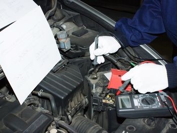
Heres a video I took during practical class testing a potentiometer TPS, using a muti-meter set to dc volts, showing how the voltage increases as I open the throttle. Using a power supply in case of an ECU I set to 5v and connected it to the VCC terminal of the sensor using alligator clips. Then using the meter I connected the red positive lead to the VTA signal wire and black lead to E2, which is earth.
Here are the throttle angles and there output voltage readings I got testing this TPS.
Fully closed: 0.79v
Quarter open: 1.42v
Halfway open: 2.29v
Three quarters open: 3.22v
Fully open: 4.26v
According to the specifications these readings are good.
Faulty TPS
The TPS contains electro-mechanical moving parts which are prone to wear and tear. A faulty TPS can result in improper data being fed to the ECU, which monitors engine performance, in respect to the fuel efficiency of the car. A damaged, malfunctioning TPS can cause variety of symptoms. Below are some examples
Symptoms of a Defective Throttle Position Sensor
Following is a list of symptoms of which, a car driver may experience because of a defective throttle position sensor:
Following is a list of symptoms of which, a car driver may experience because of a defective throttle position sensor:
- Bucking and jerking of the car.
- Idle surging of the car.
- Sudden stalling of the car engine.
- Hesitation while the driver of the car is trying to accelerate.
- Sudden surge in car's speed while driving on the highway.
A shorted TPS will produce a signal that’s the equivalent of a wide-open throttle all the time.
This will make the fuel mixture run rich and usually set a trouble code that corresponds to a voltage signal that’s too high.
If the TPS is open, the computer will think the throttle is closed all the time. The resulting fuel mixture will be too lean and a trouble code that corresponds to a low-voltage signal may be set.
Below is video off Youtube, explaing in detail the test proceure to checking the performance of a TPS. It also shows you what a faulty sensor will show and what a good sensor looks like.
http://www.youtube.com/watch?v=IsX5q3jBeBQ
ENGINE COOLANT TEMPERATURE SENSOR
Theory of Operation
The engine coolant temperature sensor (ECT) is a device that changes resistance as the temperature changes. Its operating characteristic is linear, which means that when plotted on a chart the plotted line is straight. Inside the sensor is a thermostat, which is an electronic temperature sensitive variable-resistor. The ECT (thermistor) is a NTC sensor (as temperature goes up resistance and voltage goes down or vise-versa). The ECT sensor receives a 5 volt reference voltage from the ECU. The ECT works by changing its internal resistance according to coolant temperature and therefore also changing the voltage drop across itself.
The ECU uses the ECT input to determine various component operation and engine control modes. It uses the ECT signal input to make calculations for the following.
• Fuel delivery or injector pulse-width.
• Cold start enrichment mode.
• Cooling fan operation.
• Determine open and close loop initiation.
• Idle control (IAC) operation.
• Ignition timing corrections.
The ECT is also used by the ECU to control the operation of the following components.
• Delay EGR, TCC and canister purge operation on a cold engine.
• Knock corrections depending on engine temperature.
• Some systems use the ECT input to control transmission shifts points and quality.
Test Procedure
Suspend the engine coolant temperature sensor in a container of water.
Below is a picture I took in class of this step.

I heated the water and checked the temperature with a thermometer. The thermometer should NOT touch the bottom of the hot container as this might damage the thermometer or give an incorrect reading. Also check to see if there is any resistance to the body of the sensor it should read 0L.
The results are shown in the table below.
The readings above show that the resistance of the sensor changes with the temperature.

Above is a graph showing the resistance measured between the terminals.
Conditions that Affect Operation
Any condition that changes the resistance of the ECT circuit other than a temperature change has an effect on vehicle performance. High CO levels, engine flooding, faulty cooling fan operation, etc are a result of a faulty ECT sensor or circuit. An inoperative cooling system (stuck thermostat, inoperative cooling fans, etc) will also change the resistance of the thermistor inside the ECT sensor causing an engine performance problem.
Extreme corrosion at the sensors connector will lead to excessive resistance in the circuit. This will raise the sensors signal voltage leading the ECU into calculating that the engine is cooler than it is. A cold engine will make the ECU increase the injector pulse-width, creating excessive CO at the tail pipe. In extreme high resistance conditions, engine flooding can occur, since the ECU reacts as if the engine temperature is at subzero temperatures. If on the other hand, a lack (shorted) of resistance is present at the ECT circuit, the opposite of the previous will hold true. Lower than normal ECT circuit resistance will lower the voltage signal across the sensor tricking the ECU to act if the temperature is higher than what it really is, which in turn makes the ECU reduce injector open time or pulse-width. Such a condition can cause a lean misfire or even a no start on a cold engine, due to the fuel starvation effect caused by the ECU’s reduction of injector pulse width.
The ECT is also affected by the general electrolytic conditions of the coolant fluid. This turns the engine and coolant into a sort of battery. This slight acid content of the coolant will produce a small voltage, which can interfere with the sensors signal.

http://www.diycardoctor.com/images/Sensors/ECT_sensor1.jpg
The engine coolant temperature sensor (ECT) is a device that changes resistance as the temperature changes. Its operating characteristic is linear, which means that when plotted on a chart the plotted line is straight. Inside the sensor is a thermostat, which is an electronic temperature sensitive variable-resistor. The ECT (thermistor) is a NTC sensor (as temperature goes up resistance and voltage goes down or vise-versa). The ECT sensor receives a 5 volt reference voltage from the ECU. The ECT works by changing its internal resistance according to coolant temperature and therefore also changing the voltage drop across itself.
The ECU uses the ECT input to determine various component operation and engine control modes. It uses the ECT signal input to make calculations for the following.
• Fuel delivery or injector pulse-width.
• Cold start enrichment mode.
• Cooling fan operation.
• Determine open and close loop initiation.
• Idle control (IAC) operation.
• Ignition timing corrections.
The ECT is also used by the ECU to control the operation of the following components.
• Delay EGR, TCC and canister purge operation on a cold engine.
• Knock corrections depending on engine temperature.
• Some systems use the ECT input to control transmission shifts points and quality.
Test Procedure
Suspend the engine coolant temperature sensor in a container of water.
Below is a picture I took in class of this step.

I heated the water and checked the temperature with a thermometer. The thermometer should NOT touch the bottom of the hot container as this might damage the thermometer or give an incorrect reading. Also check to see if there is any resistance to the body of the sensor it should read 0L.
The results are shown in the table below.
Water temperature | Resistance |
20 | 2700Ω |
30 | 1700Ω |
40 | 1100Ω |
50 | 870Ω |
60 | 630Ω |
70 | 480Ω |
80 | 340Ω |
90 | 250Ω |
The readings above show that the resistance of the sensor changes with the temperature.

Above is a graph showing the resistance measured between the terminals.
Conditions that Affect Operation
Any condition that changes the resistance of the ECT circuit other than a temperature change has an effect on vehicle performance. High CO levels, engine flooding, faulty cooling fan operation, etc are a result of a faulty ECT sensor or circuit. An inoperative cooling system (stuck thermostat, inoperative cooling fans, etc) will also change the resistance of the thermistor inside the ECT sensor causing an engine performance problem.
Extreme corrosion at the sensors connector will lead to excessive resistance in the circuit. This will raise the sensors signal voltage leading the ECU into calculating that the engine is cooler than it is. A cold engine will make the ECU increase the injector pulse-width, creating excessive CO at the tail pipe. In extreme high resistance conditions, engine flooding can occur, since the ECU reacts as if the engine temperature is at subzero temperatures. If on the other hand, a lack (shorted) of resistance is present at the ECT circuit, the opposite of the previous will hold true. Lower than normal ECT circuit resistance will lower the voltage signal across the sensor tricking the ECU to act if the temperature is higher than what it really is, which in turn makes the ECU reduce injector open time or pulse-width. Such a condition can cause a lean misfire or even a no start on a cold engine, due to the fuel starvation effect caused by the ECU’s reduction of injector pulse width.
The ECT is also affected by the general electrolytic conditions of the coolant fluid. This turns the engine and coolant into a sort of battery. This slight acid content of the coolant will produce a small voltage, which can interfere with the sensors signal.

http://www.diycardoctor.com/images/Sensors/ECT_sensor1.jpg
Below is a video off Youtube explaining the operation of the ECT sensor
http://www.youtube.com/watch?v=ZuCVzUarefE
This is good but you need more stuff for faulty readings, what could cause it to go bad etc. And you need to add quite a lot more sensors/actuators to be a complete blog. Remember - "theory" then "testing procedure" and then "reflection on good vs bad results" with what would it take in order for that sensor/actuator to go bad
ReplyDeleteiv updated to your comment
ReplyDelete